Beach Drive Coastal Resiliency Project
Engineering a more resilient shoreline to protect the residents and infrastructure of the Village of Fox Point.
Engineering a more resilient shoreline to protect the residents and infrastructure of the Village of Fox Point.
The Beach Drive Coastal Resiliency Project was triggered by a series of storm events beginning in Fall 2019. The storm of October 2019 significantly damaged the shoreline. The Village began to document the erosion and formulate a plan of action for emergency protection of the shoreline. In early 2020 the Village had the large concrete blocks installed as an emergency but temporary measure. The system helped to lessen the erosion but was heavily damaged again in December 2019 and January. In January 2020, the Village submitted a coastal resiliency grant to FEMA and, in August 2020, selected the project in order to aid the Village of Fox Point in engineering a more robust and resilient shoreline. Below is the Project History leading to the FEMA Grant.
Project History Timeline of significate damage leading into FEMA Grant Funding and the project
In March 2021, the Village of Fox Point hired the team of MSA and FreshWater Engineering to develop a plan to be implemented in 2022. The process begins with the development of concepts for public review. A comprehensive plan will be the basis for the construction documentation that is required to implement the enhancements. The improvements to the shoreline may include relocation or repairs may include relocation or repairs to utilities along Beach Drive. Below is the project schedule for the Beach Drive Coastal Resiliency Project.
Timeline for the Beach Drive Coastal Resiliency Project
Milwaukee County has documented and georeferenced several aerials in their Geographical Information System (GIS) beginning with photos from the 1930's. The aerials of the shoreline along N. Beach Drive illustrates the shifting and eroding edge. Below are enlarged views of the southern shoreline where Village utilities are directly affected by the eroding shoreline. The aerials used for the diagrams are 2018 and 2020 which indicate there has been upwards of 10 feet of shoreline lost in a 2-year period in some locations. The Village further documented the erosional loss by surveying the shoreline from October 2019 through April 2020 and, in some cases, noted up to a 7 foot loss of shoreline in a six week period. Working with Wisconsin DNR and the Army Corps of Engineers these aerials will help to identify where the shoreline protection can be placed. Wisconsin Emergency Management (WEM) will coordinate FEMA Grant assistance with the Village.
The Village of Fox Point is outlined in red. The project sites are the highlighted dots
Lake Michigan Water Levels from 1918 to present
The Army Corps of Engineers lake data was used to establish lake levels for the comparison aerial photo shown below. Note: the 2020 aerial includes the existing survey created for the Beach Drive Coastal Resiliency Project.
Recent Lake Michigan Water Levels
2018 Aerial Photo (move >right)................................South Project Site (North End of Site)...............................2020 Aerial Photo(move<left)
2018 Aerial Photo(move>right)................................South Project Site (Center of Site)...............................2020 Aerial Photo(move<left)
2018 Aerial Photo(move>right)................................South Project Site (South End of Site)...............................2020 Aerial Photo(move<left)
Pre 2019(move>right)...........Eroding Shoreline...........2020(move<left)
The Village of Fox Point began to keep a photographic record of the shoreline at the time of the fall 2019 storm. After that event the Village continued to document shoreline erosion in subsequent storm events until the winter of 2020. MSA had begun to photo inventory shoreline conditions in May 2021 and will continue to monitor the conditions during the Coastal Resiliency Project. A selection of photographs are located to the left of the Google Earth site map below. These photos are georeferenced to the location where they were taken. Select a photograph to enlarge the view of both the photo and its location then click on the X at the bottom of right of the to get back to the overall site map and thumbnails.

Significant shoreline erosion

Expose storm pipe and eroding shoreline

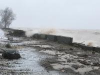
Shoreline flooding and debris

Short-term protection being dislodged

N. Beach Drive and shoreline after initial cleanup

Short-term protect dislodged

Waves overtopping a sanitary manhole

Erosion around structure

Storm line packing from lake sediments

Destructive forces from lake ice

Significant shoreline loss at a sanitary MH

Implementation of concrete blocks
Waves overtopping the short-term protection

Overtopping of the short-term protection

The concrete block dislodged from wave impact

Displaced concrete blocks

Eroded discharge channel

Displaced concrete blocks and overtopping

Temporary stacking of blocks to limit overtopping

Sand and sediment collection

View of blocks from N. Beach Drive

North site temporary shoreline stabilization

Dislodged temporary concrete blocks

Lower blocks overtopped and shoreline erosion

Block step access to water
Significant shoreline erosion
Expose storm pipe and eroding shoreline
Shoreline flooding and debris
Short-term protection being dislodged
N. Beach Drive and shoreline after initial cleanup
Short-term protect dislodged
Waves overtopping a sanitary manhole
Erosion around structure
Storm line packing from lake sediments
Destructive forces from lake ice
Significant shoreline loss at a sanitary MH
Implementation of concrete blocks
Waves overtopping the short-term protection
Overtopping of the short-term protection
The concrete block dislodged from wave impact
Displaced concrete blocks
Eroded discharge channel
Displaced concrete blocks and overtopping
Temporary stacking of blocks to limit overtopping
Sand and sediment collection
View of blocks from N. Beach Drive
North site temporary shoreline stabilization
Dislodged temporary concrete blocks
Lower blocks overtopped and shoreline erosion
Block step access to water
Revetment is a term for the stone cross section used to stabilize shorelines and protect against waves on water bodies like Lake Michigan. The stone is place in 2 to 3 layers which consist of small, core layer and a much larger armor stone outer layer that take the wave impacts. The armor stone is sized by wave modeling (computer model based on US Army Corps of Engineers recommendations) of the Lake. The model determines the weight of the stone required to stay in place and not be dislodged. The weight of the stone determines the physical size of the stone. Applying various slopes in the study of the revetment create differing scenarios of the width and height of the protection as well as final stone sizing. Below are variations of revetment slopes and heights based on the model created for the Village of Fox Point's shoreline for this project. The colored lines reflect the slope of stone on the Lake Michigan side from 1.5:1 to 5:1 slopes. The steeper the slope (i.e. 1.5:1) the higher the stone will be in order to fully protect the shoreline from wave overtopping and back of stone erosion and undercutting. Typically the land side of the revetment is 1.5:1 (as shown) or 2:1 at most.
The Beach Drive Coastal Resiliency Projects consist of 2 sites. The north site is between 8035 and 8005 N. Beach Drive and the south site extends from 7535 to 7405 N. Beach Drive.
A 2.5:1 slope is shown on Concept A starting at the top of shoreline from 2018 prior to the 2 storm events. The side by side plans shown the revetment at the north and south ends of the site verses running the length of N. Beach Drive along the lake edge.
In Concept B the revetment is shown at a 5:1 slope projecting further out into Lake Michigan and inward toward N. Beach Drive to account for the wider footprint required for the lesser slopes. The height of the revetment would be lower in Concept B than A as shown in the revetment cross sections above.
The south shoreline site includes an existing sanitary sewer line located along the edge of the shoreline. At the time the line was constructed the shoreline was much further out than today. The concepts strive to maintain the sanitary line in its current location by providing variations that protect the system from further erosion. The sanitary line is approximately 16 feet deep and relies on gravity to flow to a lift station that pumps up to the top of the bluff to the Village system. The sanitary line is shown in red on all of the concepts.
The shoreline in Concept A is protected entirely by stone. The revetment is shown at a 2.5:1 slope. Stormwater line outfall locations into Lake Michigan are shown behind the revetment for further protection from wave impacts and sediment loading. Some storm lines have been realigned to reduce the number of outfall locations along the shoreline. Drainageways are added to illustrate how the water will flow from the pipes through the revetment to Lake Michigan. A trail is shown meandering through the open space between N. Beach Drive and the revetment. Landscape and sloping topography along the back of the revetment will lessen the visible stone from N. Beach Drive and residents.
Below are photographs of revetment which show the outer armor stone. The armor stone can include large flat stones for public access to the water via ramping or steps built into the revetment.
Revetment armor stone layer
The image below shows Concept A with the 2018 shoreline (black dashed line) and 2020 shoreline (yellow dashed line) with the revetment which will maintain stability while reducing further erosion.
In Concept B the revetment includes a vertical wall at the top of the shoreline to reduce the footprint of the protection as will as allow for a 4:1 slope of stone that will reduce the height of the revetment. The wall can be made of a modular concrete unit that has the mass to provide enough weight required for wave protection. The vertical wall can look on the surface like rock and blend into the site. The wall can also act as a seat wall on the N. Beach Drive side to reduce filling in behind the protection while maintaining flow for rain runoff. The stormwater lines are shown discharging in areas were the wall undulates back into the shoreline to provide protection to the outfalls. The trail is shown along the vertical wall and undulating around the storm outfalls and drainage channels. Landscape enhancements provide buffers from the drainageways and introduces native wetland and upland plant materials found along the Lake Michigan shoreline.
The photos below show a vertical concrete wall. The image on the left is a residence on Lake Michigan in a northern suburb of Chicago. The blocks are stacked and use weight and design to stay in place. The center images is also on Lake Michigan and illustrates the a potential view of a seat wall from the N. Beach Drive side of the shoreline.
Modular block wall on Lake Michigan Potential seat wall at walk Natural stone steps in the armor stone
Concept B with the 2018 and 2020 aerial photographs
In Concept C the revetment is shown at a 3:1 slope and entirely of stone. There may be a potential need to add vertical walls inward by the stormwater outfalls to provide enough height for wave overtopping. Most likely the depth of the revetment to the outfalls will provide enough wave run to not require walls or as many walls. Further model will provide the technical information is carried forward to final plans.
When the project moves into construction documentation, strategies will be developed to how the revetment will be constructed. Below are photos of land side installation verses from the water (barge). Both photographs are sites on Lake Michigan near the Village.
Revetment construction from land
Revetment construction from water
Concept C with the 2018 and 2020 aerial photographs
A vertical wall running the entire length of the shoreline is shown in Concept D. In this scenario the wall in combination with a lessened, 5:1 slope illustrates providing a footprint similar to the other concepts but with less steep slope in the revetment a lower height at the top of the shoreline protection would be required. The trapezoidal shape created by sloping the revetment becomes large as the slope is lessened as in this case to 5:1. The help offset the width of the revetment a vertical wall could significantly reduce the width. In this concept the stormwater outfalls would be in the wall and flow over the top of the armor stone. Given the reduced slope of 5:1 the wave impact and potential sediment loading would be lesser on the outfalls given the length of travel over the armor stone.
With closer inspection, the example photograph from Concept B shows the stormwater drain pipe (teal green) integral to the wall.
Stormwater pipe penetrating through the modular wall
Concept D with the 2018 and 2020 aerial photographs


